
SOUNDWICH DIY
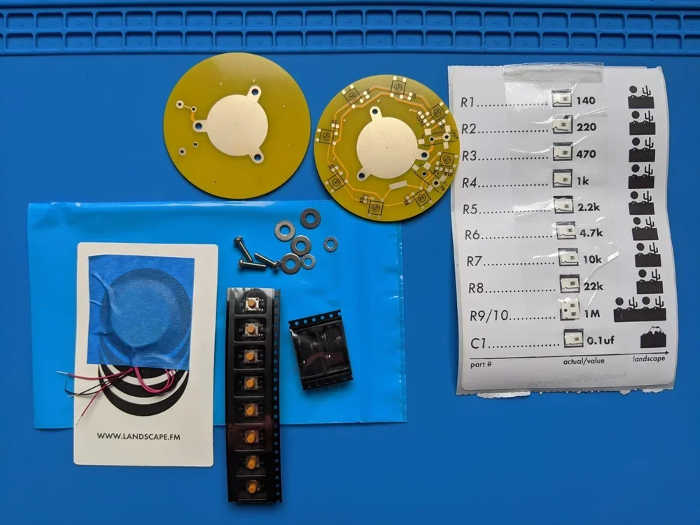
*Check that you have all the pictured parts in your kit:
top and bottom pcbs
2 Piezos, with wires attached
8 tack switches
2 3.5mm audio jacks
3 machine screws
4 large washers
2 small washers
SMT parts sheet, with attached 10 resistors and 1 capacitor
Tools you’ll need: Thin gauge solder / Soldering iron / Tip cleaner (wet sponge, wet paper towel, wire tip cleaner) / Tweezers / Wire clippers / Small Philips Head screwdriver / A fan to blow the fumes away from your lungs / Blue or paper tape
To remove parts from the SMT parts sheet, pull downwards on the clear tape until R1 is uncovered. Stop there. Use your tweezers to pull the part out of its little plastic casing. To keep from getting the parts mixed up, only remove R2 after soldering R1, and so on.
**Before starting it can be helpful to scroll downwards through the images to see the progression of the build.
Take Caution: When soldering, do not touch the underside of the PCB as the copper will become extremely hot and may burn your flesh. Make sure to only work on a surface that is heat resistant cause you’ll melt your desk. Do not touch the Piezo disks with bare skin while soldering them to the PCB.
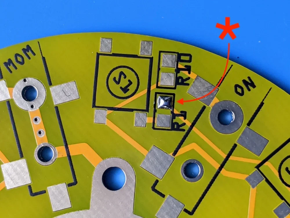
On the bottom PCB, apply a small amount of solder to one pad each marked R1 through R10 as well as one pad of C1. Also apply solder to one of the four pads marked S1 through S8.
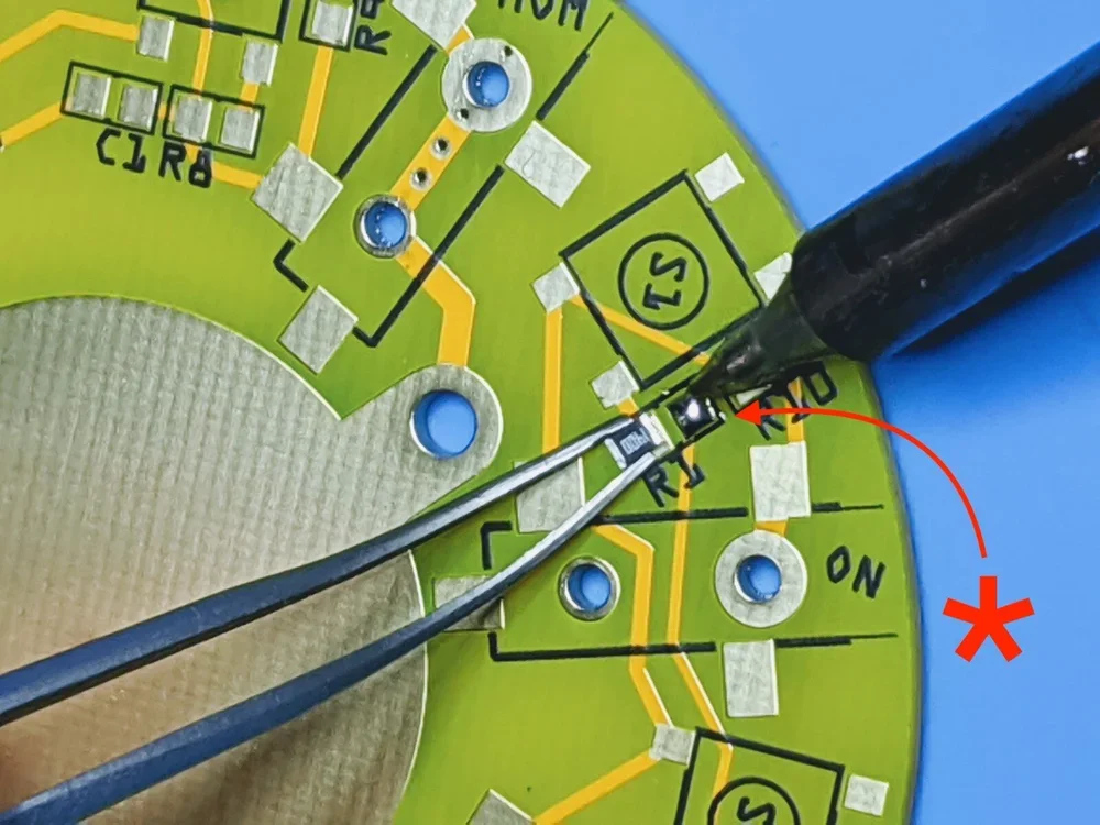
If you have never soldered surface mount components before here is a simple rundown. (Also I highly recommend watching a tutorial on surface mount soldering on youtube before beginning.) Grasp resistor R1 with the tweezer with one hand. Use your other hand to heat the solder (on the PCB) very briefly while pushing the resistor into the melted solder. Quickly remove your soldering tip from the board while holding the resistor steady, centered on R1 (between the soldered and unsoldered R1 pads) while the solder cools (a couple seconds). Now solder the remaining pad of R1 before moving to the next resistor. As with all electrical components too much heat for too long can kill the part.**See photos below
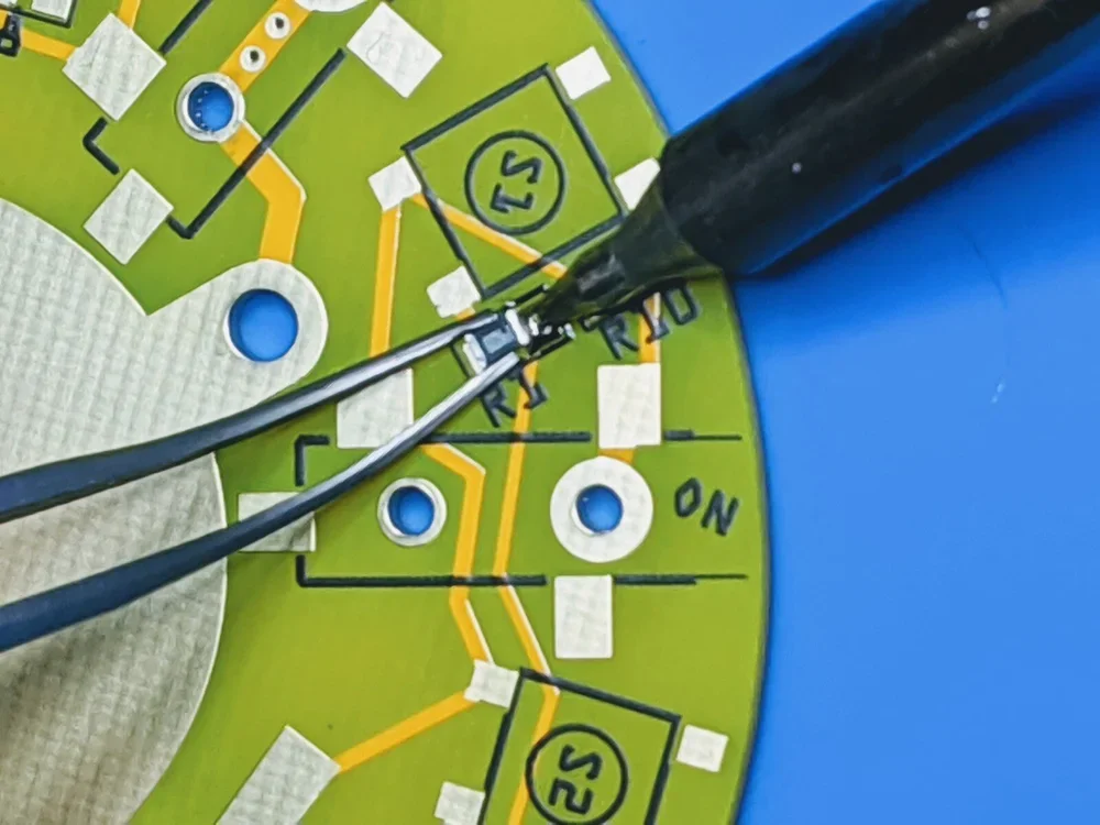
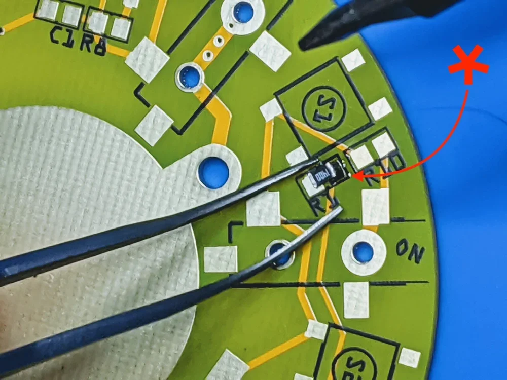
This is acceptable, but try to center the part better than I have done here.
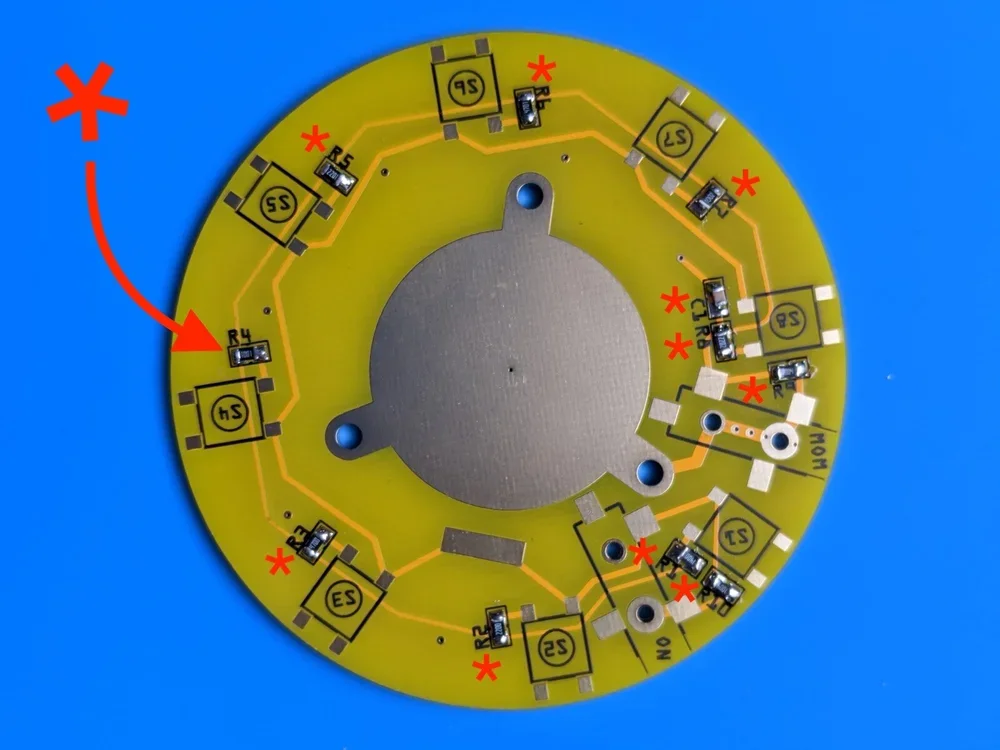
Solder resistors R1-R10 and capacitor C1, following the same directions as above.
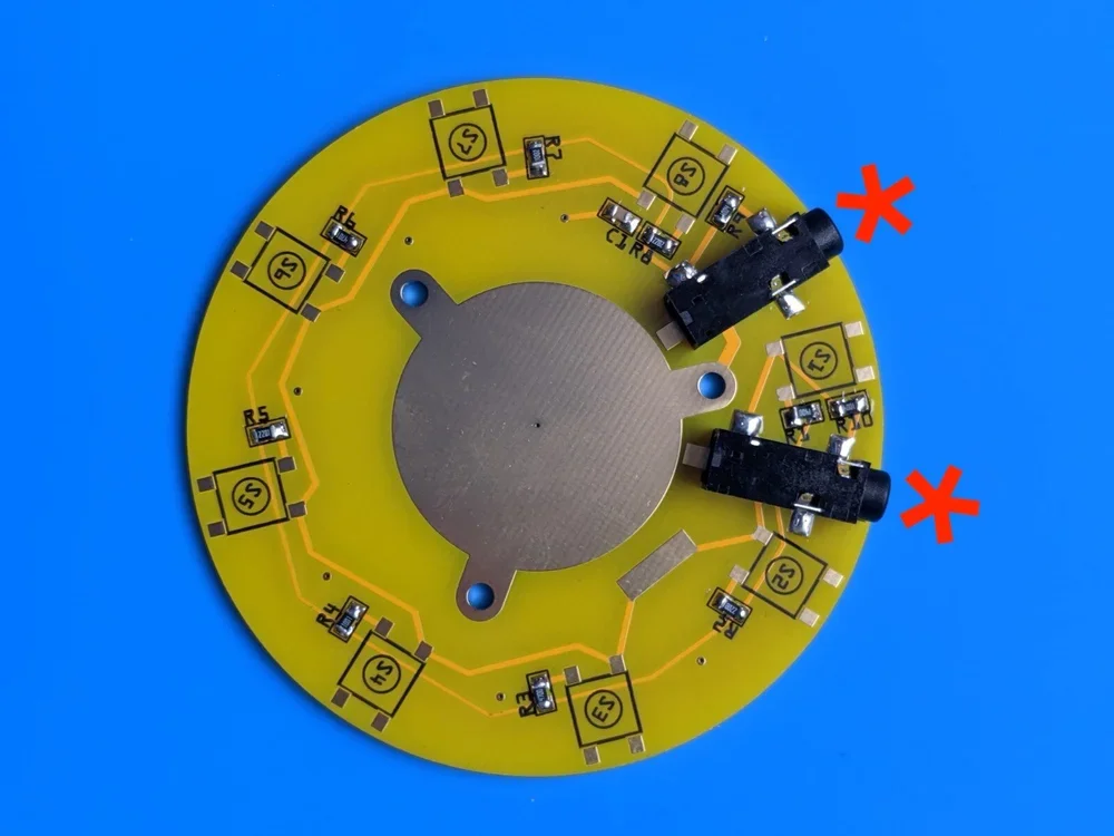
Place the 3.5mm jacks (ON and MOM) so you feel the small alignment pins seat into the two small holes below. Solder the three legs.
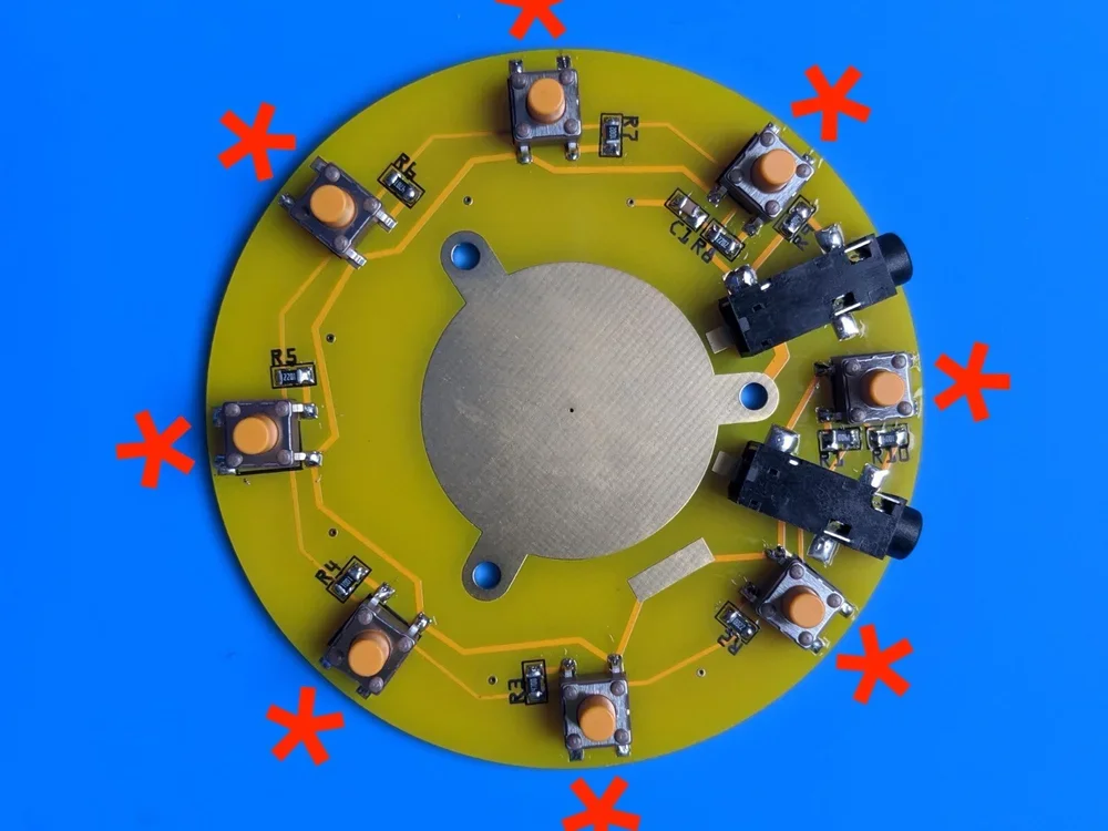
Place the 8 tact switches (S1-S8) using the same technique used as the resistors. Add solder to only one of the four pads and slide it into place while heating the solder. Once aligned, solder the 3 remaining pads before moving onto another switch.
Note: Take this time to go back over every solder connection point as they’re very easy to miss! See photo below for example of me missing two points on the top left switch.
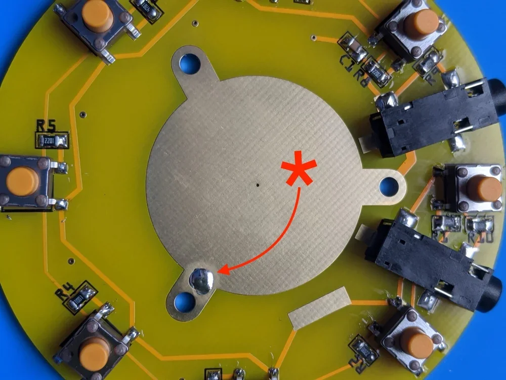
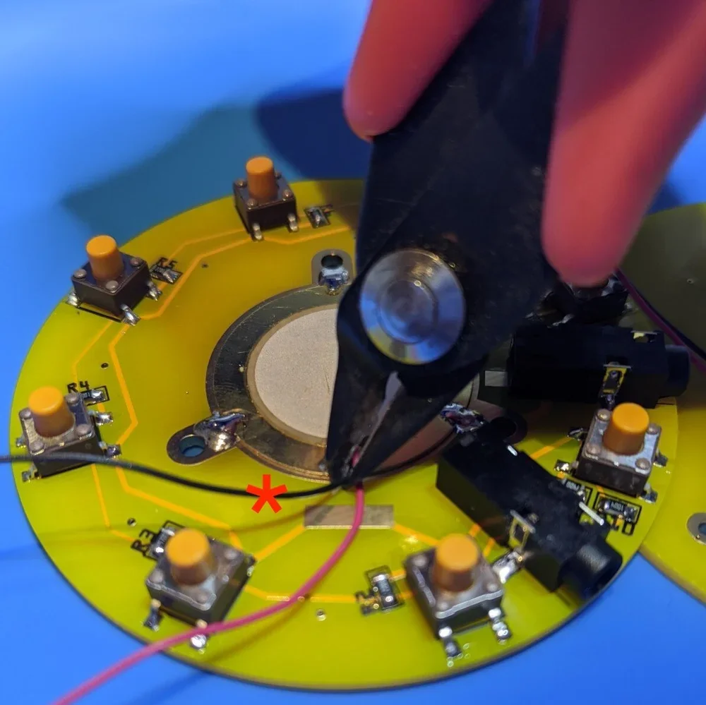
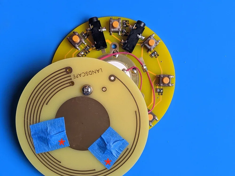
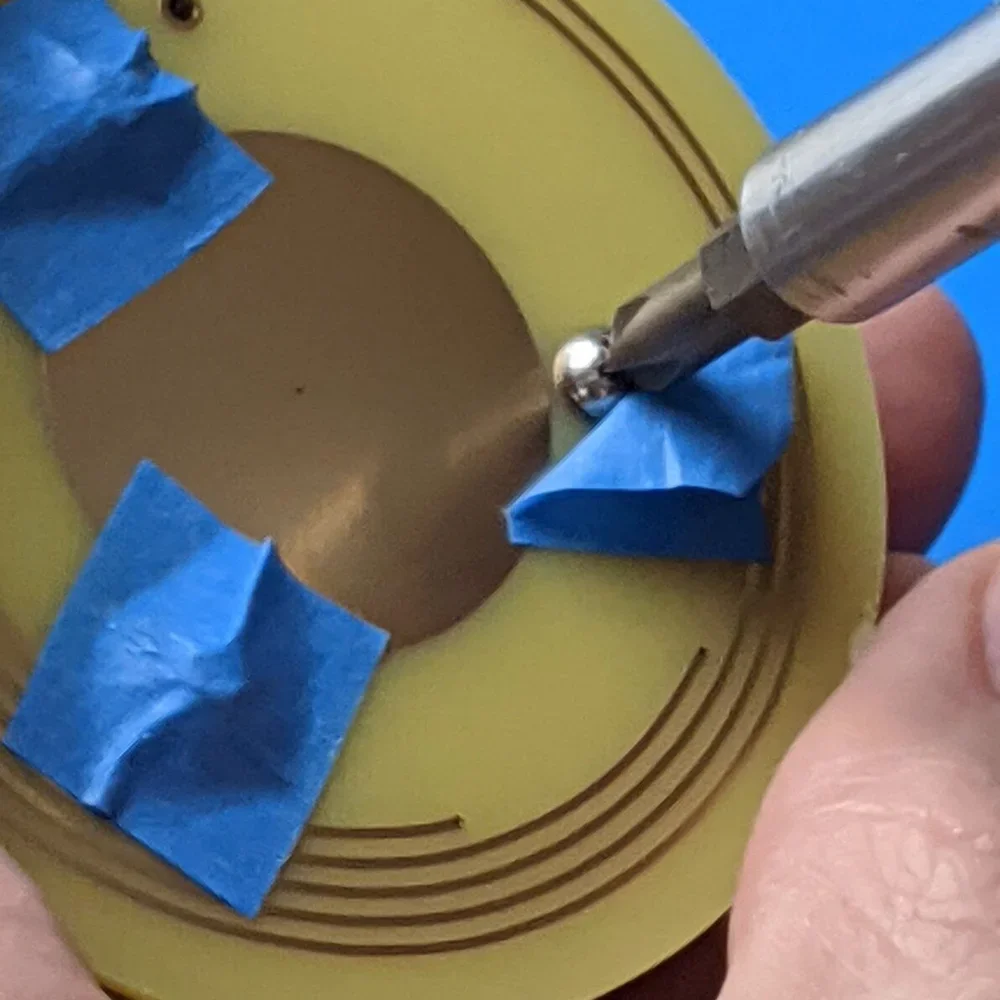
Then, install the Piezo. Center the Piezo disk and place a small amount of blue tape to one side while soldering the first of three locations. Take Caution! Do not use your fingers to move the Piezo into place because the metal of the Piezo will become extremely hot very quickly. See below for what NOT to do. Consider using a small piece of cardboard or your tweezers to scoot the disk into place taking care to keep the disk flat against the PCB for as much contact as possible.
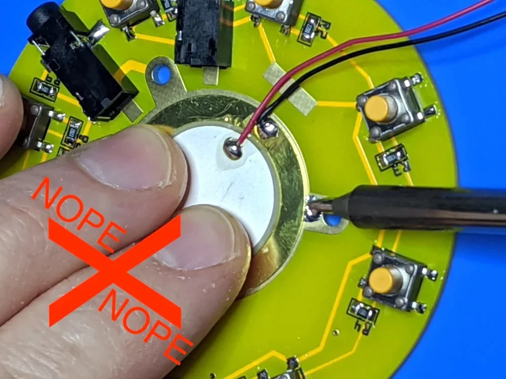
Nope.
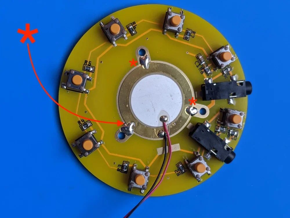
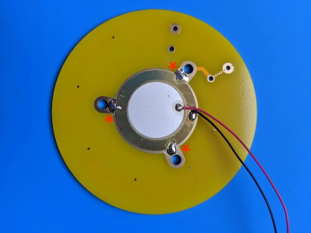
Now add solder to all three points directly next to the screw holes while taking care to not get any into the holes themselves. Notice how the solder spans across the disk and PCB surface for a secure hold. This also helps to ensure a loud signal.
Repeat the same Piezo-soldering steps for the top PCB.
Snip/remove the black ground wire from the bottom Piezo. You won’t need it.
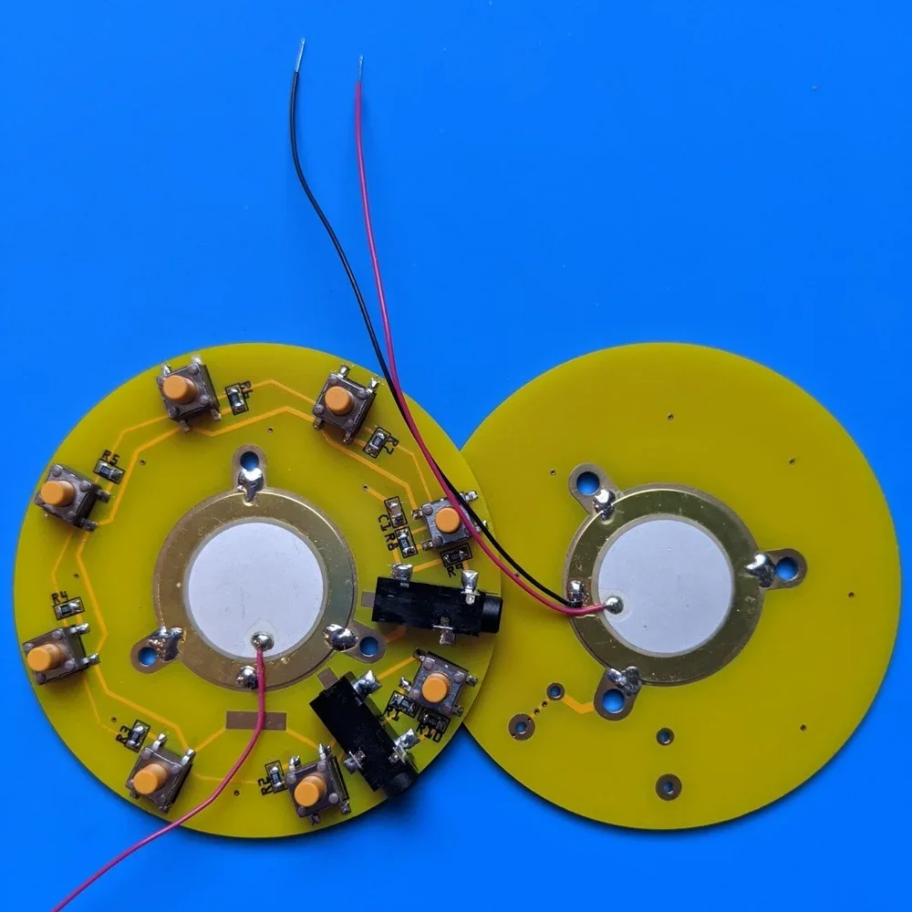
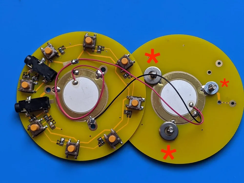
Place the two finished PCBs side by side like this.
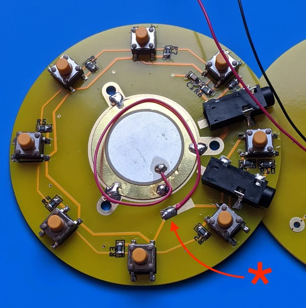
Solder the bottom Piezo’s red wire to the long rectangular pad.
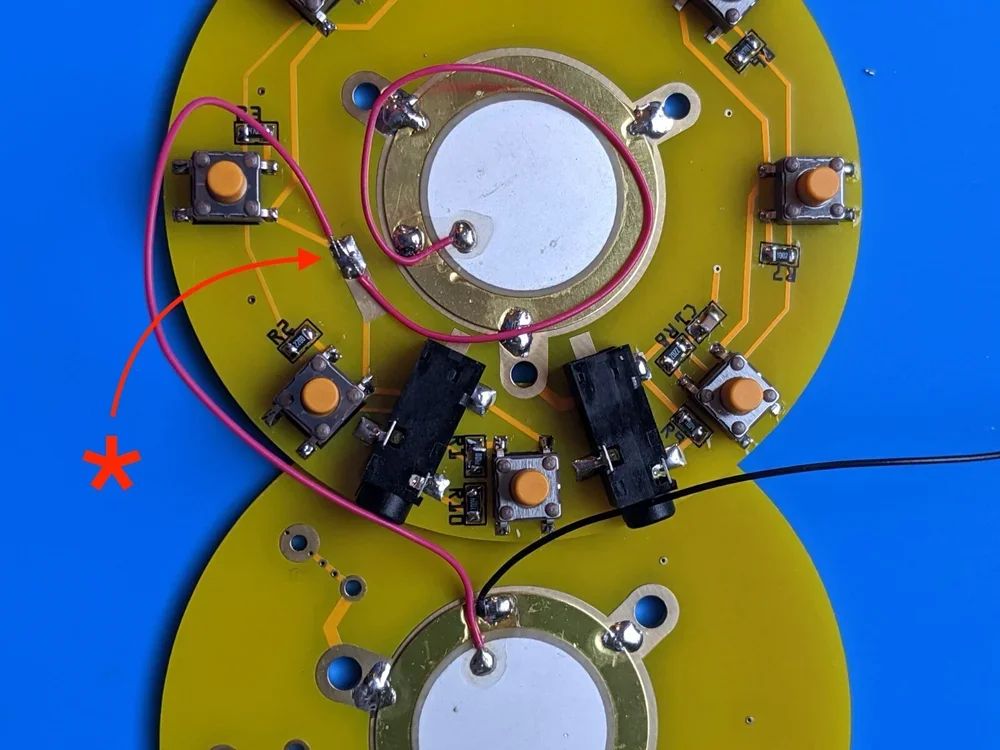
Solder the top Piezo’s red wire to the same pad as well. *You may need to tape down the bottom red wire before soldering the top red wire to keep it from moving during soldering.
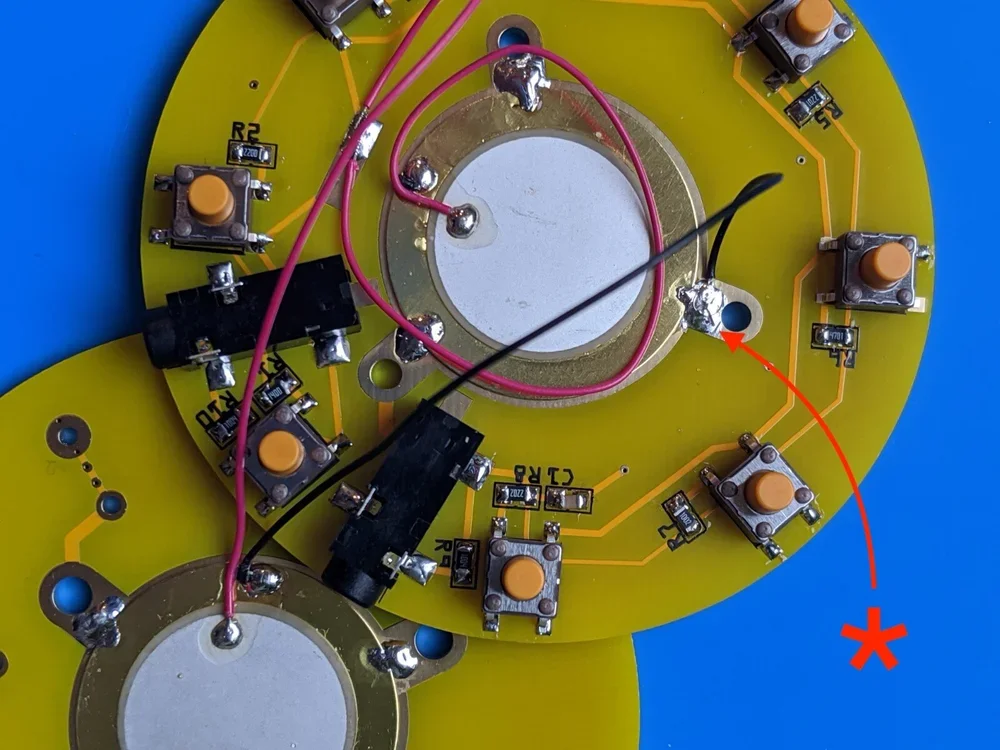
Solder the black wire between both Piezos.
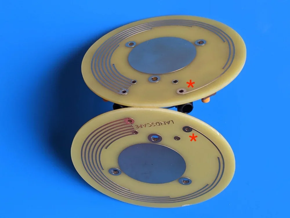
Once all three wires are attached *carefully lift both PCBs and mirror them for proper alignment.
Insert all three machine screws. Use three small pieces of the blue tape to hold them in place for the next step.
Once taped, flip both PCBs over again and place all 6 washers on the machine screws. You’ll notice that 2 of the washers are smaller than the others. These are to be used on the screw which mounts between the 3.5mm jacks.
Carefully close the PCBs together like a book (as to not lose the washers). While bringing them together vertically, make sure the machine screws are connecting with their matching holes on the main PCB assembly. *Note: before you begin tightening the screws make sure that the disks are aligned nicely with one another and stop screwing before they are fully tight. While holding the Soundwich together with one hand, remove the tape from one screw and begin gently screwing them together with a small Phillips head driver. Continue to inspect the disk alignment as you attach in the remaining screws.
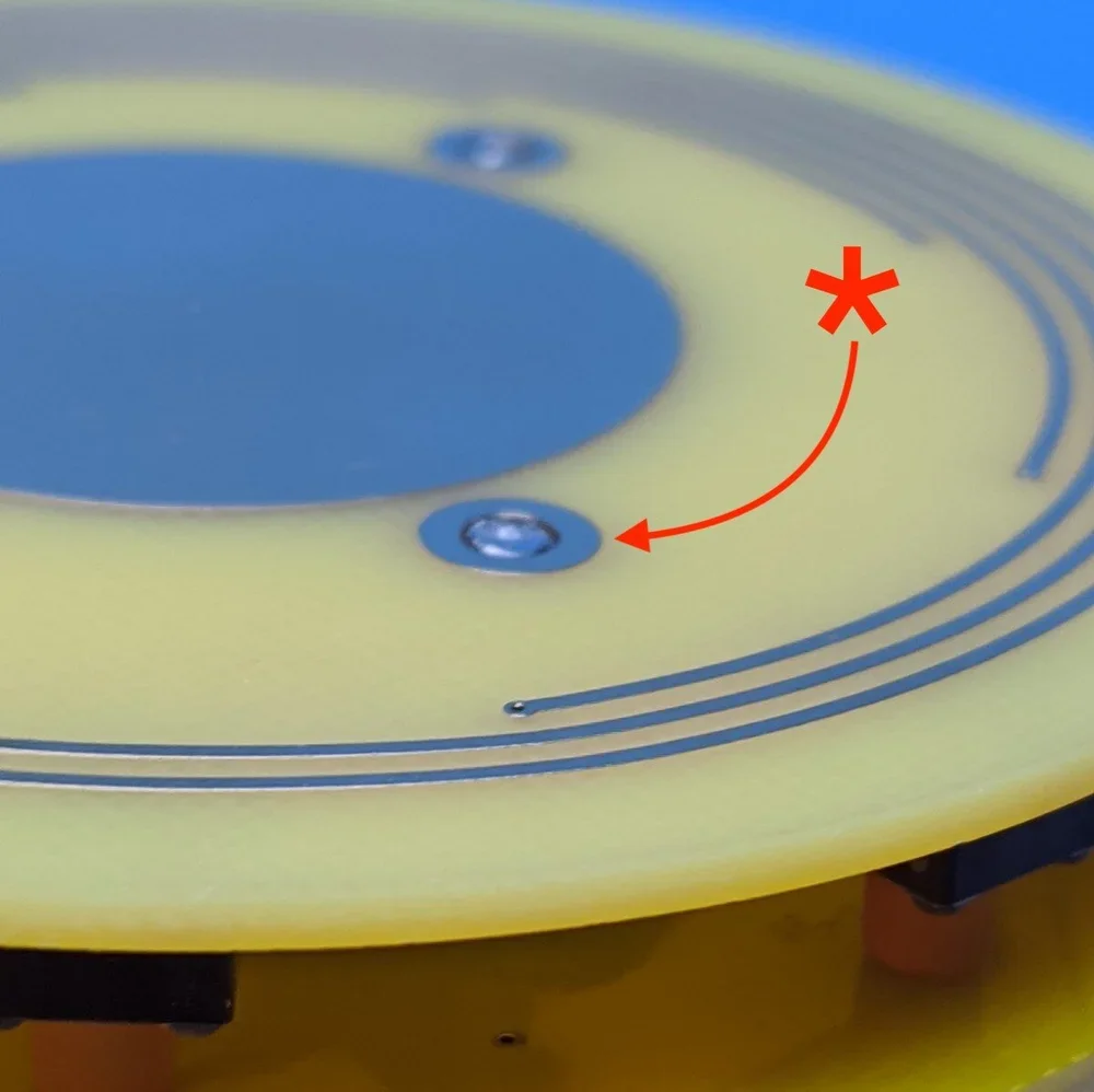
If the machine screws are sticking out from below, back them out just slightly until flush with the bottom.
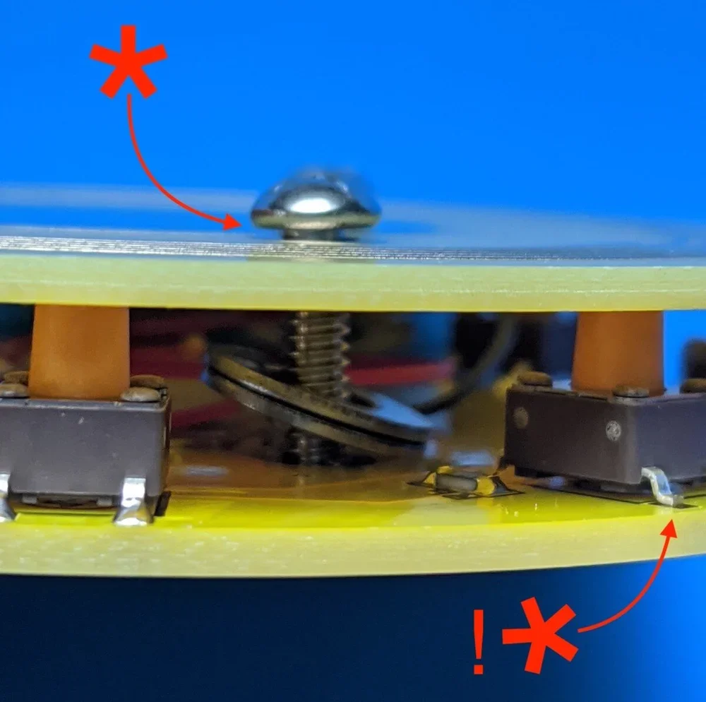
Inspect the top to ensure there is a little space between the bottom of the screw and the top of the PCB. !*Look I missed another solder joint.
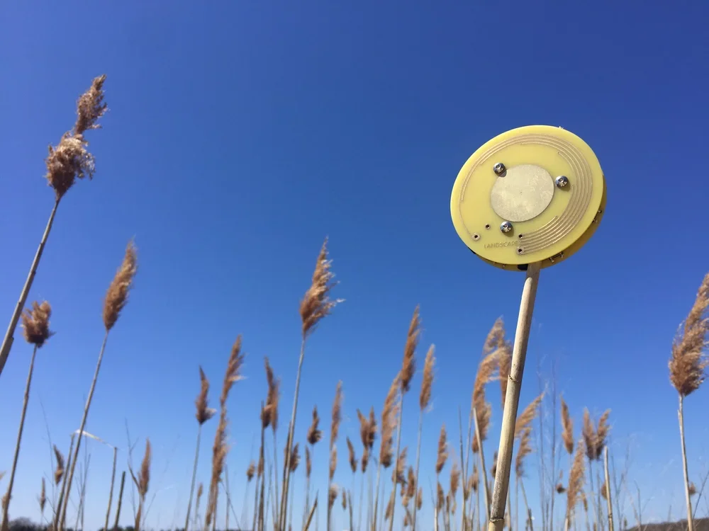
You’re done! Plug your Soundwich into a mixer or effects box and see if it makes clicks, and shaker noises.
© 2015-2026 landscape